Posted by rbanffy 6/30/2025
For the LED eyes, I created THT connectors using the ends of the dupoint wire ends.
https://makerworld.com/en/models/672277-wabbt-wifi-bluetooth...
My initial hope was that doping PLA, PETG or some other material with a conductor and then applying strong variable magnetic field near the print head to force creation of conductive domains while the filament is amorphous and hot. This turned out to be not feasible, as O3 explained to me repeatedly, over hours of chats.
A simpler and surprisingly workable solution appears to be adding a second printing head loaded with tin. Tin is not as good as copper - but it's still leagues ahead of conductive filaments. To offset the poor conductivity you can use thin, but very broad traces.
A speculative approach would work like this:
1. Print PETG layers using a regular filament, but leave "baths" for tin traces. A bath should be an opening at least 2-3 millimeters tall, to account for the surface tension.
2. After N layers, fill the baths from the tin head. Tin melting point is near PETG, but it would cool rapidly and, hopefully, weld to the plastic.
This way you could probably integrate a pcb into a print. I haven't tried that, but i recall people actually trying to print with tin - so that part is at least not a complete fantasy.
Fiber laser etching is the way to go, the required equipment is already below $2000, and the process is quite simple. Additionally manufacturing copper/aluminium is next to impossible at home, considering their melting points.
You could even use a pre-masked copper plate (which is less reflective than copper), so your PCB would come with a mask.
The components will still be the same, so you'll still need some kind of pick-n-place functionality to make anything, so why not just have another print head for making the traces / doing the PnP?
The head could lay copper wire/foil tape for conductors and do standard PnP from trays / reels of components, which you'll need either way.
It would be a little more geometrically limited than what this post imagines, but it would have the upside that it would actually work today and with most real electronics applications, unlike the low performance conductors made via conductive polymers as the OP's process imagines.
https://www.swtest.org/swtw_library/2013proc/PDF/SWTW13-22.p...
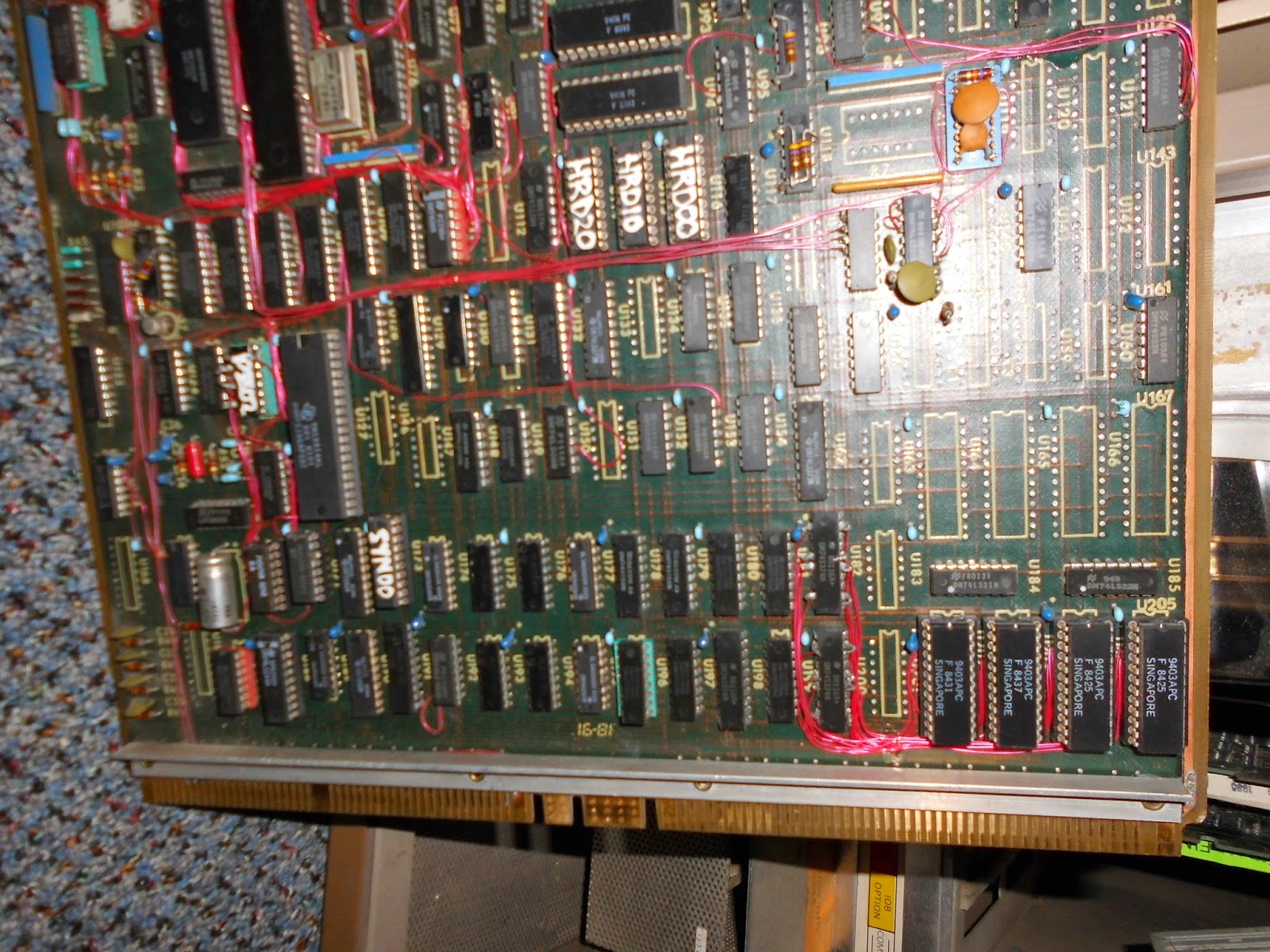
I believe this technique was used in the Three Rivers PERQ computers. Here is an image of one of their PCBs https://blogger.googleusercontent.com/img/b/R29vZ2xl/AVvXsEg...
Sounds awesome, but this is an extremely hard problem to solve. You can't simply lay down wire or foil into arbitrary shapes on 3D surfaces.
Some geometries wouldn't work, but it would be sufficient to make shapes like you see in breadboard connections (up, zigzag around, down)
I would probably slightly overbuild the plastic and then use a heated tool to form the smoother surfaces the wire/foil would go in/on.
I've also seen laser sputtering of copper, etc. which could be the another approach, something similar is used for metalizing plastic already, though contamination would need to be controlled to maintain low resistivity.
If the base material was thermally conductive you could have a heatsink block with the circuit embedded in it.
I'm sure it's never wise to underestimate a materials scientist.
3D Printing the PCB itself is pretty much impossible for any non-trivial application. Doing multi-layer PCBs with 0.20mm wide traces, spaced 0.20mm apart? Forget it, not happening - and requirements like those are standard for hobbyist-level chips like the RP2040 these days.
And if you're not printing your own PCB, what's left is module-level assembly and connectivity. In other words, just printing a bunch of wires.
It might be tricky printing PLA directly to copper clad PCB, but then you could expose the board to UV or etchant to make the PCB traces. Then remove the PLA plastic to expose the copper traces.
Slightly modifying/abusing the cheap DLP resin printers is more effective because they're essentially a controllable UV mask anyway.
It was pitched back in 2017 as a "Multimaterial & Electronics" printer. Got to half a million or so in pledges before some of the backers uncovered serious red flags and Kickstarter suspended the campaign.
Hope this effort fares better.
I don’t see the advantage of this approach. You end up with a worse and less reliable circuit just to avoid the single chemical step.